Introduction
This report outlines the development of a residential ground floor plan and front elevation, products of the application of computer-aided design (CAD) tools. It illustrates how AutoCAD can embody the precision, clarity and professionalism required of a successful architectural work. The assignment uncovers design choices, technical assumptions, and administrative strategies that were employed to clearly identify the building layout and elevations.
Project Requirements and Assumptions
The project had two AutoCAD outputs - a ground floor plan and a front elevation in 1:100 with dimensions and notes, and as professionally presented as practicable. There was not sufficient information on the details required, so the design, for some dimensions, was based on reasonable assumptions (Mashrabboyev, 2025). The external walls were assumed as 300 mm cavity walls, with internal partitions at 100 mm; the height of floor to floor was set at 2.38 m; doors were presumed at 0.91 m wide; and window sills 1 m above floor level. Strip foundations were 600 mm width x 750 mm depth, plus a duo-pitch roof, as with typical residential practice, the required assumptions were made for inputs into the house and land package.
Methodology: Use of AutoCAD Tools
The drawings were developed through AutoCAD to ensure accuracy and legibility. The drawing process followed the steps outlined within AutoCAD, including the creation of layers specifically for walls, windows, doors, and dimensions(Chappell, 2015). Last was applied the correct scale and a title block was used to identify the project and relevant information. When completing the drawings, it used dimension tools to verify accuracy, and the use of labelled symbols indicated design intent (Zahedi et al., 2022). In cases such as ensuring that elevation detail aligned with the floor plan involved issues, it resolved them using construction lines and updating layer properties. The conventions of line weight, symbols, hatching/toning and dimensioning gave the drawings a professional consistency.
Ground Floor Plan Design
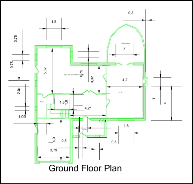
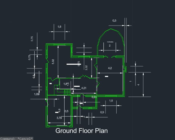
Figure: Ground Floor Plan
Decisions Relating to Internal Layout
The design aims to separate multiple functional areas, including the entrance hall, lounge, kitchen/dining area, conservatory, toilet and garage (Ifitkhar et al., 2024). Each of the spaces was placed with the intention to maximise circulation and usability. The entrance hall is located adjacent to the staircase and provides direct access to circulation on other floors. The lounge is located next to the conservatory, allowing for natural light and further socialising space; the kitchen and dining area are located centrally on the plan and are well serviced from the other areas in the building. The garage is located relatively close to the main route of circulation to ensure it is accessible from the outside, as well as connected to the building.
Walls, Doors and Windows
All external cavity walls are consistently 300 mm, and internal partitions are consistently 100 mm, and usable doors are all at 0.91 m. The positioning of doors supported circulation, accessibility, and layout without conflict with windows or internal positioning (Mitton and Nystuen, 2021). Positioning of windows was important for natural light and ventilation, since sills need to be at 1 m above floor level. Larger windows have been used in aggregated areas (e.g. the lounge and conservatory) so the daylight penetration was increased; small openings are for service areas like the toilet. CAD snapping tools and ortho has been applied, so spacing is measured consistently and elements are aligned in appropriate positions.
“From Concepts to Construction - Expert Architecture Assignment Help You Can Trust.”
Circulation Space
The plan prioritises effective circulation between the rooms. The central hallway acts as the primary circulation space, giving access to the lounge, kitchen/dining room, and stairs. The doors were placed based on logical walking corridors to minimise wasted space, while making circulation to all functional zones easy for everybody. The staircase was located adjacent to the entrance and consists of 14 risers of 170 mm and 200 mm treads, and allows vertical circulation to begin without interfering with the arrangement of the ground floor.
Usability Considerations
The orientation of each room was carefully considered with respect to usability. The kitchen and dining room are centrally-located at the heart of the home, neighboring both the lounge room and entrance, enabling a swell connection to how the home ebbs and flows. The lounge room was oriented to maximize comfortable and connection to the conservatory, which is a bright light filled extension to each living space. The garage and vehicular access were located to be easily accessible but still contiguous with internal functional areas via the hallway. The ditch toilet was located right by the entrance hall so that it is easily accessible but does not intrude on the main living space of the house.
Using AutoCAD Features for Precision
AutoCAD features assisted in precision. It created layers for structural walls, openings, and annotations. It used the dimension tools to ensure the dimensions were accurate, and it used hatching to identify wall build-ups. It inserted the title block before the drawing was finished so that it could be populated with project information. Construction lines, orthogonal locking and snapping commands assisted in aligning the windows and doors; it made identifying the details contrasted with the architectural drawings easier. It used blocks for producing the repeated parts, such as doors and windows, and it assisted in reducing errors and maintaining standards.
Front Elevation Design

The front drawing is a drawing of the external facade of the residential building as viewed from the front. This drawing is produced in AutoCAD and shows the disposition of the walls, doors, windows, and roof structure, while also demonstrating dimensional accuracy and construction details (Joshua et al., 2024). These drawings will be used alongside the ground floor plan as a vertical projection to depict, explain and show the external aesthetics and proportions of the building.
Elevation Drawing Explanation
The elevation shows a two-storey building with clear architectural elements. The garage door is on the left side and matches the ground floor plan. The main entrance door is in the middle between two windows, reflecting the way the interior spaces are zoned. The window drawings are the standard residential casement-style with a sill height of 1 m and were evenly distributed between each floor to maintain daylight and venting. The roof was drawn as a duo-pitch roof, consistent with the message presented in the assignment brief, both of these roofs produced a balance on the elevation, and symmetry of outline.
Consistency with the Ground Floor Plan
The elevation was carefully coordinated with the ground floor plan to verify accuracy. The positioning of the doors and windows in the elevations is directly identified with the location of the doors and windows in the internal layout (Pexman et al., 2021). The large window at the gable end above the garage relates directly to the upper living area, while smaller windows relate to service areas, like bathrooms. The dimensions of both garage and entrance for instance, were drawn as per the details in the plan, providing a coherent design. The elevation heights were drawn to unadjusted floor to floor level heights of 2.78m for the ground level, and 2.83m for the first level and there is a +/- overall height of approximately 7.3m from the ground to the top of the gable, which is consistent with earlier assumptions.
Consequential and Aesthetic Considerations
The elevation was realised for technical accuracy and aesthetic balance. The symmetry of the window formation creates a visual rhythm for the facade, which could otherwise lead to visual imbalance (Samalavičius, 2021). The entrance door is proportioned appropriately and set in a proportionately appropriate place to promote usability. The drawing demonstrates a realistic wall thickness, the depth of the footing, and its relationship to the other levels in a load-bearing sense.
“Precision in Every Line - Expert AutoCAD Assignment Writing Service.”
Detailing
Dimensioning or dimensioning was consistently presented through the elevation to identify building heights, wall lengths and window locations (Altun, 2022). At the base foundation and its details were supplied to show the strip footings 600 mm wide x 750 mm deep, with the top of the foundation being 450 mm below ground. Notes and dimensions clearly indicate structural assumptions for contractors or other readers. Even though the elevation is line-based, traditional hatching conventions were illustrated to indicate materials. For example, cavity wall hatching fills were provided, and roof slopes were written with slope angle lines.
Architectural Detailing & Technical Considerations

The drawings have a floor-to-floor height of 2.38 m, using stairs at 14 risers of 170 mm with 200 mm treads to be usable. The roof ridge height was chosen at 7.3 m, following a duo-pitch truss design. Foundations were assumed as 600 mm wide, 750 mm deep strip footings with TOF at 450 mm below ground. Data in the walls (thickness) doors (width) windows (sill height) were based on building regulations. All notes, reactions and dimensions are matching allow them to be clear, compliant and constructable in professional practice.
Appendix
|
ACADEMIC YEAR 2024/2025 |
|||||||||||||||||||||
|
CAD & BIM-M30156-FHEQ_4 |
|||||||||||||||||||||
|
|||||||||||||||||||||
Drawing 1: Ground floor plan of house internal layout
Drawing 2: Elevation from the front
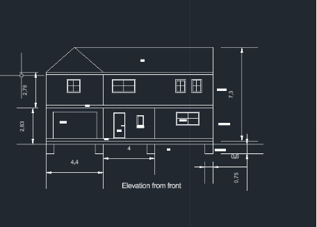
Figure 2: Elevation from the front
Figure 3: Drawings with title block
Figure 3: Drawings with title block
Conclusion
This report met the requirements of generating a ground floor plan layout and front elevation, using CAD and following industry standards and conventions. CAD proved invaluable for the clarity, precision, and communication of architectural intent. The assignment improved technical ability, informed design reasoning and ultimately reflected an understanding of professional drawing conventions.
References
- Altun, A.F., 2022. Determination of optimum building envelope parameters of a room concerning window-to-wall ratio, orientation, insulation thickness and window type. Buildings, 12(3), p.383.
- Chappell E, 2015. AutoCAD Civil 3D 2015 Essentials. Autodesk Official PressOnstott S, 2015. AutoCAD 2015 and AutoCAD LT 2015: Essentials. Autodesk Official Press
- Iftikhar, S., Ammar, M.F., Din, M. and Ahmed, A., 2024. Analyzing Privacy in Frank Lloyd Wright's Prairie Style Homes Through Syntactic Methods using “A Graph” and Depth Map X Softwares.
- Joshua, J.A., Usoro, A.D. and Edward, D.I., 2024. Effect of Revit and AutoCAD Softwares on Students' 3D Skill Performance in Modelling Building Drawings in Technical Colleges in Akwa Ibom State. International Journal of Vocational Studies and Library Science, 5(1).
- Kilmer, R. and Kilmer, W.O., 2021. Construction drawings and details for interiors. John Wiley & Sons.
- Mashrabboyev, H., 2025. EVALUATING THE EFFECTIVENESS OF PROJECT-BASED LEARNING IN TEACHING ENGINEERING DRAFTING USING AUTOCAD. Модели и методы в современной науке, 4(9), pp.207-212.
- Mitton, M. and Nystuen, C., 2021. Residential interior design: A guide to planning spaces. John Wiley & Sons.
- Pexman, K., Lichti, D.D. and Dawson, P., 2021. Automated storey separation and door and window extraction for building models from complete laser scans. Remote Sensing, 13(17), p.3384.
- Samalavičius, A.L., 2021. Revisiting facades: A note on symmetry as an aesthetic principle. Symmetry: Culture and Science, 32(3), pp.405-420.
- Zahedi, A., Abualdenien, J., Petzold, F. and Borrmann, A., 2022. BIM-based design decisions documentation using design episodes, explanation tags, and constraints. Journal of information technology in construction, 27.

UPTO55%
Avail The Benefit Today!
To View this & another 50000+ free