Software process
The working method of creating a three-storey building model in Autodesk Revit consists of a set workflow that integrates the aspects of setting up a project, modeling, and documentation. The initial process is the creation of a new project using the Architectural template, ensuring that the project units are established to the millimetre to have consistency with the construction drawings. These are quantified to represent the Ground, First, Second, and Rooftop stages. The first floors serve as the vertical construction of the building, and show how the boundaries of the walls, floors, ceilings, and the roof should be placed.
Then, grids and columns are given as per the position. Interpretation of Grids can provide a means of referencing property through the precise positioning of structural and architectural components. Columns can be inserted in a strategy when supporting structural framing without crosscutting with elements like windows and doors. External walls of the cavity and internal walls of the partition are modelled on each floor, keeping the wall thicknesses and alignments the same. Doors and windows are inserted to fit the designs, which are parametrically flexible in size and location.
Once the wall system has been placed, the creation of levels by adding predefined floor build-ups allows the formation of floor assemblies. The structure is finished with a flat roof with the necessary 600 mm overhang, which has been modelled with roof slab tools. Internal specifications are also inclined to include furniture and fittings to provide one with a realistic picture of the way in which the space is used.
The views and documentation are produced with the building elements in place. Revit renders automatically floor plans, the elevations, and 3D views, and those directs can be arranged on sheets and plotted. External dimensions are put in the wall centres and internal dimensions on the wall faces. Line weights and visibility properties are changed to satisfy the need for plotting in black and white.
Design

Figure 1: External wall
The figure denotes the external wall specification, and the height of the wall is 6096 mm. In the wall section, three levels are presented such as core boundary, structure, and layer below. The total thickness of the wall is 150 mm, and the outer layer's width is 0 mm.

Figure 2: Internal wall
The figure denotes the internal wall specification, and the height of the internal wall is 6096 mm. There are three levels presented such as the core boundary, the structure, and the layer below. The total thickness of the wall is 90 mm, and the outer layer's width is 0 mm.
Ground Floor Plan Design

Figure 3: Ground floor
The layout of the ground floor is rationalised, and spaces in the three-storey building are presented rationally. It includes an entrance lobby that links with a lift and staircase to provide vertical transport. The plan features several bedrooms, including a master bedroom with an attached bath. These bathrooms are shared and arranged in a row. A contemporary kitchen, dining and lounge area has been opened that improves the modern lifestyle needs, whereas a study and WC add-on to the utility. There is a clear definition of circulation with central corridors that ensure circulation in spaces. The Length of the building site is 24000 mm, and the width of the building site is 19767 mm. On the ground floor, a total of fourteen rooms is presented with proper dimensions. The length of the master bedroom is 4370, and the width of the master bedroom is 3720 mm.
First and Second Floor Layout

Figure 4: First floor
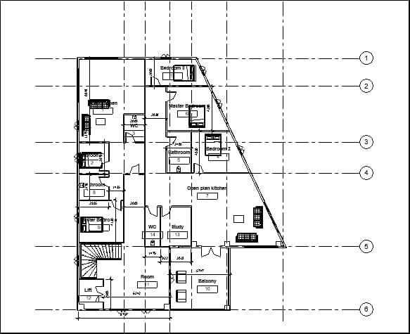
Figure 5: Second floor
The design of the first and second floor plans is well organised with residential functionality. They offer several bedrooms per hill, and shared master bedrooms and bathrooms are placed in convenient places. Large open-plan kitchen, dining and lounge spaces allow people to enjoy sharing accommodations, to be more comfortable and usable. The accessibility has been supported by a central landing that is joined to the lift and the stairwell. The other details comprise study and WC as per demand. Both floors have a balcony, and this balcony is supported by a column, and this column is also used to support the roof.
Building Elevations

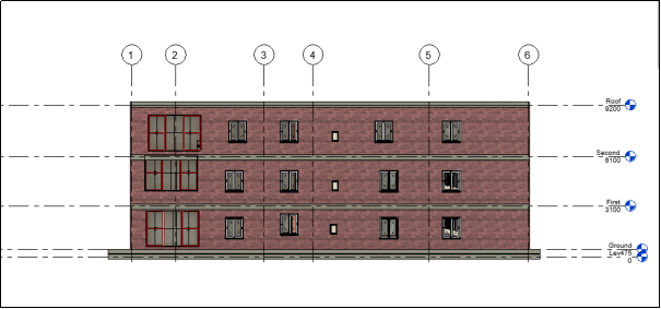
Figure 6: East elevation
The figure represents the east elevation of the building, which includes five levels: level 0, ground, first, second, and roof. The height of the ground floor is 475 mm, the height of the first floor is 3575 mm, the height of the second floor is 6675 mm, and the height of the roof is 9775 mm.

Figure 7: North elevation

The building elevation of the proposed three-storey structure is a contemporary design style and a functional design. The south face elevation focuses on an equal distribution of windows and doors that allows natural light to enter the building and open windows providing airflow throughout the building. The frontage also has a flat roof, which forms a shading effect and adds a horizontal sweeping line. The exterior wall system consists of cavity passes, which are both long-lasting and thermally efficient. In order to increase structural symmetry and rhythm of visuals, vertical alignment of openings across the floors is utilised. The entrance to the ground level is very pronounced, and the lift and stairwell in the middle point to the authority of the central circulation elements. The balconies of the upper floors and broad windows have been included to create openness as well as a sense of comfort for the users.
3D Modelling and Rendering

Figure 10: 3D model
The figure denotes the 3D model of the building and here three floors are shown. The front section has a balcony with seating elements. Big windows are presented in the front section that are used to let in the sunlight and reduce the use of artificial light. One column is designed in the front section of the building, which is used to provide the support system of the balcony and roof.
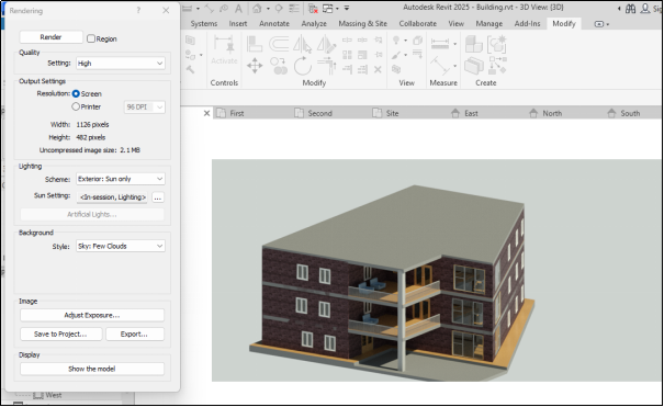
Figure 11: Rendering
The figure denotes the rendering operation of the building, and here, high-quality rendering is chosen. The sunlight scheme is chosen to make a good-quality visualisation after rendering.
The actual visual impression of the building through the rendering of the three-storey building is realistic, reflecting both the materiality as well as form of the building. Exterior walls are smooth in finish and are decorated with the incorporation of windows to ensure increased natural lighting. The design of the depiction brings out the spatial configuration of the balconies and open-plan spaces, with the design conveying the feeling of living with openness. They can be enhanced by the inclusion of landscaping items and context. The rendered model is a reasonable indication of design purpose and is a demonstration of functionality and a professional architectural presentation that can be used as a submission.

Figure 12: Internal view
Figure 13: Internal view
Door and Window Schedules
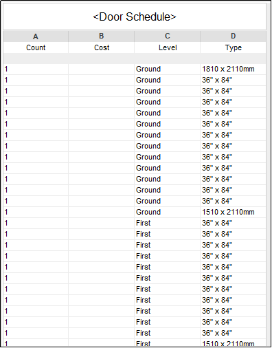
Figure 14: Door schedule
The figure denotes the door schedule, and this operation is done using the schedule option. Here, three variables are presented such as the count of doors, the level, and the type or dimension of the doors.

Figure 15: Window schedule
The figure denotes the window schedule, and this operation is done using the schedule option of the Revit software. Here, three variables are presented such as the count of windows, the level, and the type or dimension of the windows
Big Data Principles in Cloud Computing: Critical Analysis and Design
Calculation
- Storey height = 3.0 m (floor-to-floor)
- External wall centreline perimeter Lext = 64 m
- Net footprint (per floor) Af = 160 m²
- RC slab thickness ts = 0.20 m; density = 24 kN/m³
- External wall thickness = 0.30 m; internal partitions = 0.115 m
- Openings in external walls = 25% of wall area
- Flat roof overhang = 0.60 m all round
Areas
- GIFA (per floor): Af=160 m2
- Total GIFA (3 storeys) = 3Af = 480 m2
- Roof plan area (without overhang) = Af =160 m2
- Overhang area (approx.) Aoh = Lext×0.6 = 64×0.6 = 38.4 m2
- Total roof cover = 160+38.4 = 198.4 m2
Walls
- Gross external wall area (all storeys)
- Aw,g = Lext×height×3 = 64×3×3 = 576 m2
- Net external wall area
- Aw,n = 0.75×Aw,g=432 m2
Slabs (RC)
- Volume per floor Vs = Af×ts = 160×0.20 = 32 m3
- Total (3 floors) = 96 m3
- Self-weight (uniform load) ws = ts×24 = 0.20×24 = 4.8 kN/m2
- Total per floor =Af×ws=160×4.8=768 kN
- Quick usability deductions
- Stair core = 12 m², lift = 6 m² per floor
- Usable area per floor = 160−18 =142 m2
Cost
- GIFA = (160 m² × 3 floors) = 480 m²
- RCC slab volume = (0.20 m × 160 m² × 3) = 96 m³
- External wall area = 432 m²
- Roof area = 198.4 m²
- Windows = 115 m²
- Internal partitions (allow) = 300 m²
|
RCC slab m² |
15,000 |
|
external wall m² |
2,400 |
|
partitions m² |
1,400 |
|
windows (uPVC dbl-glazed) m² |
6,000 |
|
doors |
8,000 |
|
floor finishes m² |
1,000 |
|
waterproofing m² |
600 |
|
MEP allowance m² |
2,500 |
|
lift (1 no) |
12,00,000 |
|
stair & balustrades |
2,50,000 |
|
siteworks |
3,00,000. |
|
RCC slabs: 96 m³ × 15,000 |
₹14,40,000 |
|
External walls: 432 m² × 2,400 |
₹10,36,800 |
|
Internal partitions: 300 m² × 1,400 |
₹4,20,000 |
|
Windows: 115 m² × 6,000 |
₹6,90,000 |
|
Doors: 30 no × 8,000 |
₹2,40,000 |
|
Floor finishes: 480 m² × 1,000 |
₹4,80,000 |
|
Wall/ceiling finishes (allow): 480 m² × 700 |
₹3,36,000 |
|
Roof waterproofing: 198.4 m² × 600 |
₹1,19,040 |
|
Sub-total (Works Cost) |
₹77,11,840 |
|
Preliminaries (10%) |
₹7,71,184 |
|
Design contingency (7.5%) |
₹6,36,227 |
|
Estimated Construction Cost |
₹91,19,251 |
Recommendation
The plan of the three-storey building is properly organised and functional, although there are some recommendations that can be proposed to make it more usable, efficient, and sustainable. In order to begin with, the windows should be positioned in the house to allow maximum natural lighting and air flow, which minimizes the use of artificial lighting sources and air conditioning. Larger window panels used in living and communal spaces would enhance the quality of the space. Secondly, the building would be fitted with some sustainable building features like the addition of solar panels on the flat roof, rainwater collection systems, and low-energy materials. Large balconies and open areas of the living space are also a strong point, but they reduce the outer space.
Bibliography
- Fayyaz, H., Iqbal, R., Zahra, A., Aslam, M., Rehman, M.U. and Ali, A.M., 2024. Architectural Design of a Multi-Storey Building Using Autodesk Revit Architecture. Southern Journal of Engineering & Technology, 2(02), pp.71-99.
- Maurya, A., Kumar, R., Bharadwaj, U., Rawat, P. and Kumar, M., 2021, April. Sustainable building design: energy analysis of a residential building using AutodeskRevit. In 2nd international conference on intelligent engineering and management (ICIEM) (pp. 441-446).
- Perdana, A., 2024, October. BIM-Based Simulation on Sustainable Housing Design Using Autodesk Revit. In IOP Conference Series: Earth and Environmental Science (Vol. 1404, No. 1, p. 012006). IOP Publishing.
- Waas, L., 2022. Review of BIM-based software in architectural design: graphisoft archicad VS autodesk revit. Journal of Artificial Intelligence in Architecture, 1(2), pp.14-22.

UPTO55%
Avail The Benefit Today!
To View this & another 50000+ free